
|
projectclifford repositoryclifford_lcd clifford_sim_1 left_leg_demo_new servo_driver teleop_controller ultrasonic |
Repository Summary
| Description | Quadruped Robotic Dog 🐶 based on Boston Dynamic's Spot. Controlled through a PS4 controller. With Raspberry Pi 4B as the brain 🧠. |
| Checkout URI | https://github.com/msalaz03/projectclifford.git |
| VCS Type | git |
| VCS Version | master |
| Last Updated | 2025-01-02 |
| Dev Status | UNKNOWN |
| Released | UNRELEASED |
| Tags | No category tags. |
| Contributing |
Help Wanted (-)
Good First Issues (-) Pull Requests to Review (-) |
Packages
| Name | Version |
|---|---|
| clifford_lcd | 0.0.0 |
| clifford_sim_1 | 0.0.0 |
| left_leg_demo_new | 0.0.0 |
| servo_driver | 0.0.0 |
| teleop_controller | 0.0.0 |
| ultrasonic | 0.0.0 |
README
Project Clifford
Overview (Please Read)
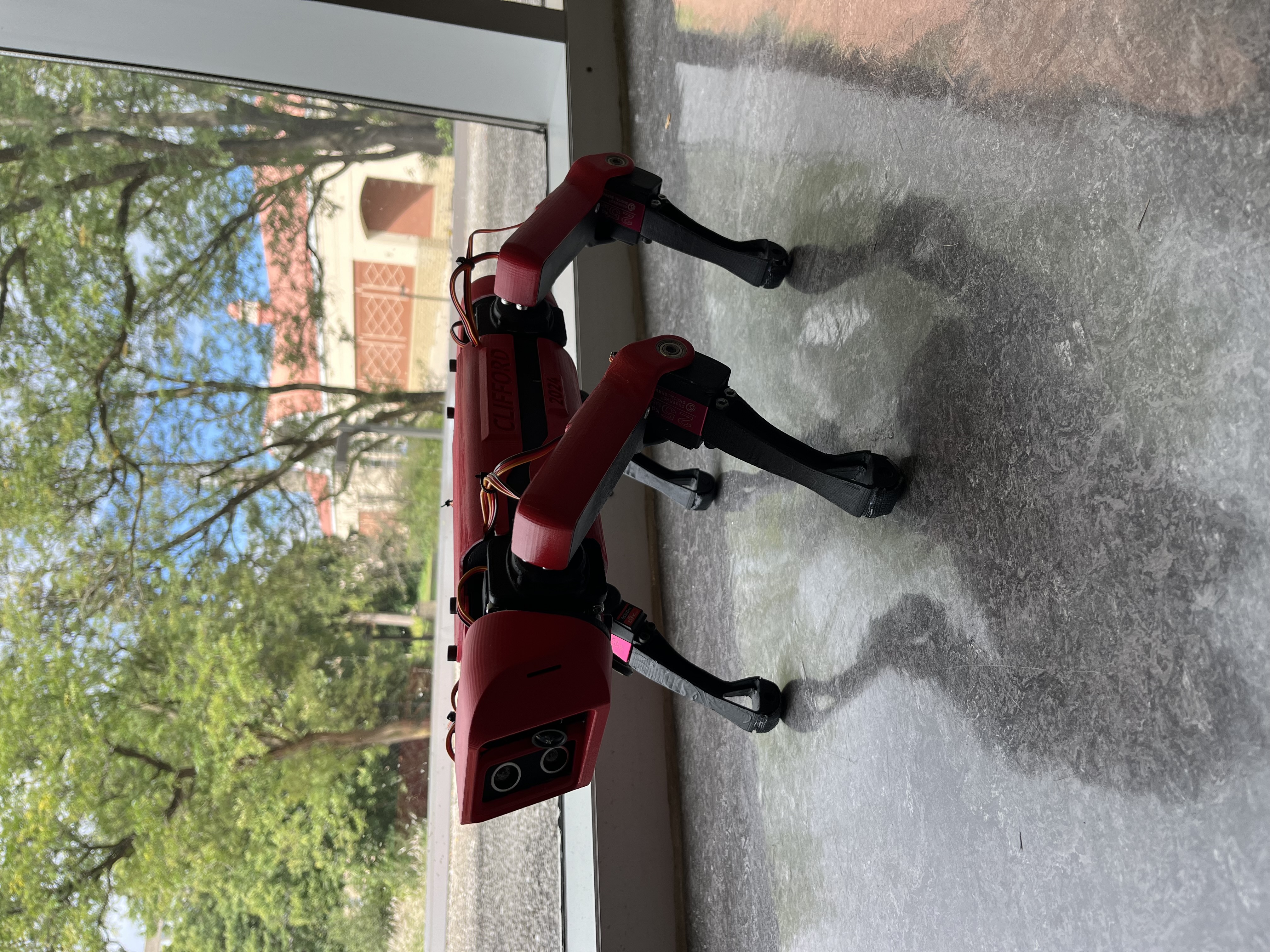
Over the past four months Cameron, Chase and I tried tackling our version of Boston Dynamic’s Spot. This repository contains the source code that interfaces all hardware interactions between our small red friend. The software includes prebuilt libraries designed for the Raspberry Pi and also references other projects similar to ours.
Now then, running on Ubuntu 22.04 LTS using ROS-Humble we went through a series of processes to organize this into a simple manner. However, we will note that they’re some poor practices as a result of time constraints and it is our first time working with the ROS framework. These will be noted and clarified further in this document. Clifford is an entirely 3D-printed project that uses inverse kinematics to simulate a dog walking. Clifford also has an FPV camera mounted which can be accessed through any web browser provided you’re on the same network as him.
Please check the references, this would have not been possible without open-source projects.
Video Demo:
https://youtube.com/shorts/WbrB4VmLomk?feature=share
Setup
The organization of nodes is not ideal. However, with time it can be reorganized neatly. Currently, we have mostly everything inside a single node. For anyone attempting to recreate anything similar please take the time to do so before programming the entire project.
Three most important folders for this project.

projectclifford_ws/
│
├── src/
│   ├── clifford_sim_1
│   │   └── ...
│   ├── servo_driver
│   │   └── ...
│   └── ...
│   ├── teleop_controller
│   │   └── ...
│   └── ...
For Using RVIZ With Clifford
To test our kinematic equations more efficiently we used RVIZ to visualize what is happening when there is a controller input. ‘clifford_sim_1’ contains a URDF file for the final version of Clifford, exported through SolidWorks URDF exporter. The launch file within this directory only launches the URDF file into RVIZ and does not contain RobotStatePublisher by default. You can enable joint-state-publisher-gui by uncommenting the related lines within the launch file or can use an additional launch file that waits for joy (controller input) and joint-state-publisher topic. The second directory relative to running RVIZ is ‘teleop_controller’ which creates a topic for joint-state-publisher.
NOTE: This totally could have been organized into a single launch file but wasn’t due to circumstances at the time.
In order to launch please do the following.
ros2 launch clifford_sim_1 clifford_sim_1.launch.py
ros2 launch teleop_controller Clifford_full_model.launch.py
For Launching and Booting Clifford
To physically launch Clifford is pretty simple (as long as you have all required dependecies), simply run the following command.
Note: At this point Clifford cannot physically turn as the turning motion was not programmed, however the kinematic equations needed to do are solved and within the software.
ros2 launch servo_driver joy_servos.launch.py
If you want don’t want to follow Clifford, you can see where he is through livestreamed footage. First identify the IPV4 address of clifford and type the following.
xxx.xxx.xxx.xxx:8081
Hardware
From researching similar projects to Clifford and our testing we sourced components that we thought were optimal for this project, consisting of two voltage regulators to isolate the power going into the servo driver and Raspberry Pi. An ADC board to measure different voltage levels into a relative percentage for battery life. A high-capacity battery to prolong battery life. LCD screen to demonstrate battery life in real time. 25 KG servos, a mixture of torque and speed to ensure smooth movements.
| Electrical Component | Model Name |
| Controller | Raspberry Pi 4B |
| Camera | Arducam 16MP Wide Angle USB Camera |
| Voltage Regulator for Pi | LM2596 |