
Repository Summary
| Description | |
| Checkout URI | https://github.com/unitreerobotics/unilidar_sdk2.git |
| VCS Type | git |
| VCS Version | main |
| Last Updated | 2025-03-10 |
| Dev Status | UNKNOWN |
| Released | UNRELEASED |
| Contributing |
Help Wanted (-)
Good First Issues (-) Pull Requests to Review (-) |
Packages
| Name | Version |
|---|---|
| unitree_lidar_ros | 1.0.0 |
| unitree_lidar_ros2 | 0.0.0 |
README
Unilidar SDK2
| [中文版 | Chinese](./README_CN.md) |
1. Introduction
This repository is the Software Development Kit (SDK) for the Unitree L2 LiDAR.
You can use the code interfaces in this repository to obtain point cloud and IMU data from our LiDAR, as well as set and get relevant configuration parameters of the lidar.
We provide several common interfaces for the LiDAR:
- The original C++ based SDK: unitree_lidar_sdk
- The package for parsing and publishing LiDAR data in the ROS environment: unitree_lidar_ros
- The package for parsing and publishing LiDAR data in the ROS2 environment: unitree_lidar_ros2
2. Coordinate System Definition
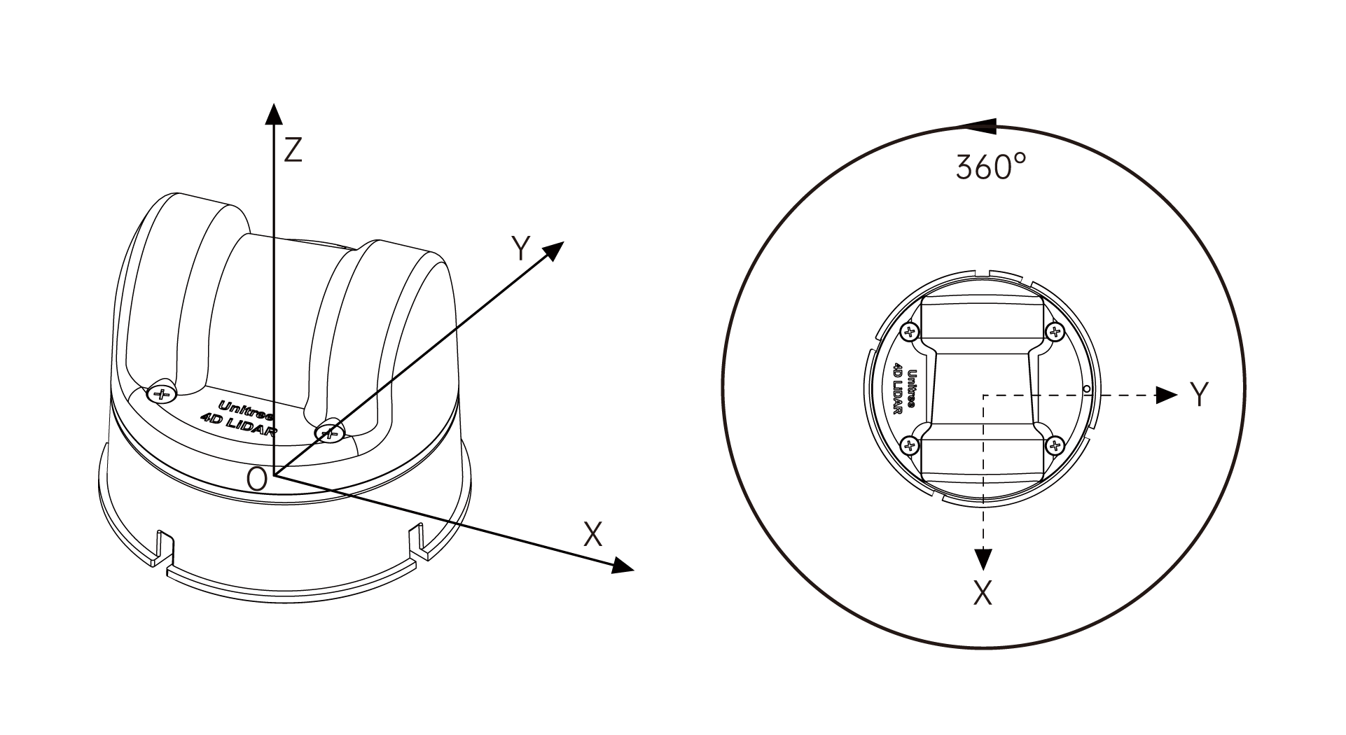
The coordinate system of this LiDAR is defined as shown in the above figure, which meets the definition of a right-handed coordinate system. Let the LiDAR point cloud coordinate system be L, and the IMU coordinate system be I.
The origin of the LiDAR point cloud coordinate system is located at the center of the bottom mounting surface of the LiDAR. Its +X-axis is opposite to the direction of the bottom cable outlet, its +Y-axis is obtained by rotating the +X-axis counterclockwise by 90 degrees, and its +Z-axis is perpendicular to the bottom surface.
The three coordinate axes of the IMU coordinate system are parallel to the corresponding coordinate axes of the point cloud coordinate system, and the two only have a translation of the origin position. The origin of the IMU coordinate system in the LiDAR point cloud coordinate system is (in meters): [-0.007698, -0.014655, 0.00667].
According to the standard transformation matrix method, the pose transformation from the LiDAR point cloud coordinate system L to the IMU coordinate system I is:
\[T_{LI} = \begin{bmatrix} 1 & 0 & 0 & -0.007698 \\ 0 & 1 & 0 & -0.014655 \\ 0 & 0 & 1 & 0.00667 \\ 0 & 0 & 0 & 1 \\ \end{bmatrix}\]3. C++ SDK
3.1 Compilation
You can compile the sample programs of this project according to the standard compilation method of cmake projects:
cd unitree_lidar_sdk

mkdir build

cd build

cmake .. && make -j2
3.2 Configuring Work Mode
The LiDAR can be configured in various working modes by default, including standard FOV or wide-angle FOV, 3D mode or 2D mode, IMU enabled or disabled, Ethernet or serial connection, etc.
We can configure the working mode through the host computer, or we can also configure the working mode through the following interface in unitree_lidar_sdk.h:
virtual void setLidarWorkMode(uint32_t mode) = 0;
Setting the working mode is implemented through a uint32_t integer variable, with each bit corresponding to the switching of a function. According to the bit position from low to high, the corresponding functions for positions 0 or 1 are shown in the following table:
| Bit Position | Function | Value 0 | Value 1 |
|---|---|---|---|
| 0 | Switch between standard FOV and wide-angle FOV | Standard FOV (180°) | Wide-angle FOV (192°) |
| 1 | Switch between 3D and 2D measurement modes | 3D measurement mode | 2D measurement mode |
| 2 | Enable or disable IMU | Enable IMU | Disable IMU |
| 3 | Switch between Ethernet mode and serial mode | Ethernet mode | Serial mode |
| 4 | Switch between lidar power-on default start mode | Power on and start automatically | Power on and wait for start command without rotation |
| 5-31 | Reserved | Reserved | Reserved |
The common usage mode is standard FOV + 3D measurement + enable IMU + power on self-start, which means these bit positions are all kept at 0. We only need to determine whether to use Ethernet connection mode or serial connection mode. For example, in the following sample program,
- If using Ethernet connection mode, configure the work mode to 0 (i.e., all bit positions of the integer variable are equal to 0)
- If using serial connection mode, configure the work mode to 8 (i.e., the third bit position of the integer variable is equal to 1, and the other 0-31 bit positions are all equal to 0)
The default factory lidar work mode is 0, i.e., Ethernet communication mode.
3.3 Running with Ethernet
The sample program for running the LiDAR with Ethernet connection is: example_lidar_udp.cpp.
First, connect your LiDAR to the computer with an Ethernet cable, then confirm that the corresponding network card of your computer is configured to the default target IP address of the LiDAR:
192.168.1.2
Then, run the sample program:
../bin/example_lidar_udp
The sample output is as follows:
``` $ ../bin/example_lidar_udp Unilidar initialization succeed! set Lidar work mode to: 0 lidar hardware version = 1.1.1.1 lidar firmware version = 2.3.3.0
File truncated at 100 lines see the full file
CONTRIBUTING
Repository Summary
| Description | |
| Checkout URI | https://github.com/unitreerobotics/unilidar_sdk2.git |
| VCS Type | git |
| VCS Version | main |
| Last Updated | 2025-03-10 |
| Dev Status | UNKNOWN |
| Released | UNRELEASED |
| Contributing |
Help Wanted (-)
Good First Issues (-) Pull Requests to Review (-) |
Packages
| Name | Version |
|---|---|
| unitree_lidar_ros | 1.0.0 |
| unitree_lidar_ros2 | 0.0.0 |
README
Unilidar SDK2
| [中文版 | Chinese](./README_CN.md) |
1. Introduction
This repository is the Software Development Kit (SDK) for the Unitree L2 LiDAR.
You can use the code interfaces in this repository to obtain point cloud and IMU data from our LiDAR, as well as set and get relevant configuration parameters of the lidar.
We provide several common interfaces for the LiDAR:
- The original C++ based SDK: unitree_lidar_sdk
- The package for parsing and publishing LiDAR data in the ROS environment: unitree_lidar_ros
- The package for parsing and publishing LiDAR data in the ROS2 environment: unitree_lidar_ros2
2. Coordinate System Definition
The coordinate system of this LiDAR is defined as shown in the above figure, which meets the definition of a right-handed coordinate system. Let the LiDAR point cloud coordinate system be L, and the IMU coordinate system be I.
The origin of the LiDAR point cloud coordinate system is located at the center of the bottom mounting surface of the LiDAR. Its +X-axis is opposite to the direction of the bottom cable outlet, its +Y-axis is obtained by rotating the +X-axis counterclockwise by 90 degrees, and its +Z-axis is perpendicular to the bottom surface.
The three coordinate axes of the IMU coordinate system are parallel to the corresponding coordinate axes of the point cloud coordinate system, and the two only have a translation of the origin position. The origin of the IMU coordinate system in the LiDAR point cloud coordinate system is (in meters): [-0.007698, -0.014655, 0.00667].
According to the standard transformation matrix method, the pose transformation from the LiDAR point cloud coordinate system L to the IMU coordinate system I is:
\[T_{LI} = \begin{bmatrix} 1 & 0 & 0 & -0.007698 \\ 0 & 1 & 0 & -0.014655 \\ 0 & 0 & 1 & 0.00667 \\ 0 & 0 & 0 & 1 \\ \end{bmatrix}\]3. C++ SDK
3.1 Compilation
You can compile the sample programs of this project according to the standard compilation method of cmake projects:
cd unitree_lidar_sdk

mkdir build

cd build

cmake .. && make -j2
3.2 Configuring Work Mode
The LiDAR can be configured in various working modes by default, including standard FOV or wide-angle FOV, 3D mode or 2D mode, IMU enabled or disabled, Ethernet or serial connection, etc.
We can configure the working mode through the host computer, or we can also configure the working mode through the following interface in unitree_lidar_sdk.h:
virtual void setLidarWorkMode(uint32_t mode) = 0;
Setting the working mode is implemented through a uint32_t integer variable, with each bit corresponding to the switching of a function. According to the bit position from low to high, the corresponding functions for positions 0 or 1 are shown in the following table:
| Bit Position | Function | Value 0 | Value 1 |
|---|---|---|---|
| 0 | Switch between standard FOV and wide-angle FOV | Standard FOV (180°) | Wide-angle FOV (192°) |
| 1 | Switch between 3D and 2D measurement modes | 3D measurement mode | 2D measurement mode |
| 2 | Enable or disable IMU | Enable IMU | Disable IMU |
| 3 | Switch between Ethernet mode and serial mode | Ethernet mode | Serial mode |
| 4 | Switch between lidar power-on default start mode | Power on and start automatically | Power on and wait for start command without rotation |
| 5-31 | Reserved | Reserved | Reserved |
The common usage mode is standard FOV + 3D measurement + enable IMU + power on self-start, which means these bit positions are all kept at 0. We only need to determine whether to use Ethernet connection mode or serial connection mode. For example, in the following sample program,
- If using Ethernet connection mode, configure the work mode to 0 (i.e., all bit positions of the integer variable are equal to 0)
- If using serial connection mode, configure the work mode to 8 (i.e., the third bit position of the integer variable is equal to 1, and the other 0-31 bit positions are all equal to 0)
The default factory lidar work mode is 0, i.e., Ethernet communication mode.
3.3 Running with Ethernet
The sample program for running the LiDAR with Ethernet connection is: example_lidar_udp.cpp.
First, connect your LiDAR to the computer with an Ethernet cable, then confirm that the corresponding network card of your computer is configured to the default target IP address of the LiDAR:
192.168.1.2
Then, run the sample program:
../bin/example_lidar_udp
The sample output is as follows:
``` $ ../bin/example_lidar_udp Unilidar initialization succeed! set Lidar work mode to: 0 lidar hardware version = 1.1.1.1 lidar firmware version = 2.3.3.0
File truncated at 100 lines see the full file