
Repository Summary
| Description | The swerve controller code for the zinger robot |
| Checkout URI | https://github.com/pvandervelde/zinger_swerve_controller.git |
| VCS Type | git |
| VCS Version | master |
| Last Updated | 2024-09-21 |
| Dev Status | UNKNOWN |
| Released | UNRELEASED |
| Contributing |
Help Wanted (-)
Good First Issues (-) Pull Requests to Review (-) |
Packages
| Name | Version |
|---|---|
| zinger_swerve_controller | 0.1.0 |
README
zinger_swerve_controller
Provides the swerve controller code for the zinger robot.
Dependencies
The configurations in this repository assume you have the following prerequisites installed on the device on which you want to run this code. That device might be an Ubuntu machine or a physical robot using Raspberry Pi OS.
-
ROS humble with the
robot_state_publisher, thejoint_state_broadcasterand the ros_control packages. - A working ROS workspace.
Also the following packages should be present:
- zinger_description - Contains the geometric description of the Zinger robot for ROS to work with.
Contents
This repository contains different folders for the different parts of the robot description.
- The config files that provide the configurations for the ROS control actuators and the test publishers
- config/swerve.yaml defines the settings for the swerve controller.
- The launch directory contains the launch files
- launch/swerve_controller.launch.py - Launches the controller node.
- The source code for the swerve controller
- zinger_swerve_controller/control_model.py - Defines the inverse and forward kinematics.
- zinger_swerve_controller/control_profile.py - Defines the body and module motion profiles.
- zinger_swerve_controller/control.py - Defines the different motion control commands that can be specified.
- zinger_swerve_controller/drive_module.py - Defines the properties for a drive module.
- zinger_swerve_controller/errors.py - Defines custom errors.
- zinger_swerve_controller/geometry.py - Defines standard geometry elements.
- zinger_swerve_controller/profile.py - Defines the motion control profile that describes how the steering angle and the drive velocity change over time when they are changed from an initial value to a target value. The only current implementation is the s-curve motion profile.
- zinger_swerve_controller/states.py - Defines the data structures used to contain information about the current motion states.
- zinger_swerve_controller/steering_controller.py - Responsible for calculating the steering angles and drive velocities of the modules based on the initial state and the desired final state.
- zinger_swerve_controller/swerve_controller.py - The controller that sends the control commands to the different joints in the drive modules. Additionally sends the odometry messages.
Kinematics
Models
The model describes the inverse and forward kinematics. There are many different algorithms available in the literature. At the moment the following algorithms are implemented:
In the future the aim is to also implement a 3D force based model devised by Neal Seegmiller and described in the following papers:
- Dynamic Model Formulation and Calibration for Wheeled Mobile Robots - 2014
- Enhanced 3D kinematic modeling of wheeled mobile robots - 2014
- Recursive kinematic propagation for wheeled mobile robots - 2015
- High-Fidelity Yet Fast Dynamic Models of Wheeled Mobile Robots - 2016
Simple kinematics model
The simple kinematic model is derived from the 2D geometric relations between the robot rotational centre and the position, angle and velocity of the drive modules. This model makes the following assumptions
- The drive modules are connected to the robot body in a fixed location and at a fixed angle.
- There is no suspension in the drive modules.
- The robot is moving on a flat, horizontal surface.
- The wheel steering axis for a drive module goes through the centre of the wheel in a vertical direction, so the wheel contact point is always inline with the steering axis.
The following image shows these relationships between the robot body degrees of freedom and the drive module degrees of freedom.
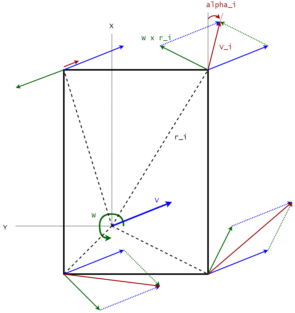
In this image the variables are as follows:
-
V- The linear velocity vector for the robot body, consisting ofV_x, the velocity in the x direction, andV_y, the velocity in the y direction. -
W- The rotational velocity for the robot body. Due to the 2D nature of the model this variable is a scalar not a vector. The rotational velocity is taken as positive going counter clock-wise. -
r_i- The position vector of the i-th drive module relative to the robot rotational centre. -
alpha_i- The angle in radians of the i-th drive module as measured in the coordinate system for that drive module. The angle is measured as positive going counter-clock wise from the x-axis of the drive module coordinate system. Note
File truncated at 100 lines see the full file
CONTRIBUTING
Repository Summary
| Description | The swerve controller code for the zinger robot |
| Checkout URI | https://github.com/pvandervelde/zinger_swerve_controller.git |
| VCS Type | git |
| VCS Version | master |
| Last Updated | 2024-09-21 |
| Dev Status | UNKNOWN |
| Released | UNRELEASED |
| Contributing |
Help Wanted (-)
Good First Issues (-) Pull Requests to Review (-) |
Packages
| Name | Version |
|---|---|
| zinger_swerve_controller | 0.1.0 |
README
zinger_swerve_controller
Provides the swerve controller code for the zinger robot.
Dependencies
The configurations in this repository assume you have the following prerequisites installed on the device on which you want to run this code. That device might be an Ubuntu machine or a physical robot using Raspberry Pi OS.
-
ROS humble with the
robot_state_publisher, thejoint_state_broadcasterand the ros_control packages. - A working ROS workspace.
Also the following packages should be present:
- zinger_description - Contains the geometric description of the Zinger robot for ROS to work with.
Contents
This repository contains different folders for the different parts of the robot description.
- The config files that provide the configurations for the ROS control actuators and the test publishers
- config/swerve.yaml defines the settings for the swerve controller.
- The launch directory contains the launch files
- launch/swerve_controller.launch.py - Launches the controller node.
- The source code for the swerve controller
- zinger_swerve_controller/control_model.py - Defines the inverse and forward kinematics.
- zinger_swerve_controller/control_profile.py - Defines the body and module motion profiles.
- zinger_swerve_controller/control.py - Defines the different motion control commands that can be specified.
- zinger_swerve_controller/drive_module.py - Defines the properties for a drive module.
- zinger_swerve_controller/errors.py - Defines custom errors.
- zinger_swerve_controller/geometry.py - Defines standard geometry elements.
- zinger_swerve_controller/profile.py - Defines the motion control profile that describes how the steering angle and the drive velocity change over time when they are changed from an initial value to a target value. The only current implementation is the s-curve motion profile.
- zinger_swerve_controller/states.py - Defines the data structures used to contain information about the current motion states.
- zinger_swerve_controller/steering_controller.py - Responsible for calculating the steering angles and drive velocities of the modules based on the initial state and the desired final state.
- zinger_swerve_controller/swerve_controller.py - The controller that sends the control commands to the different joints in the drive modules. Additionally sends the odometry messages.
Kinematics
Models
The model describes the inverse and forward kinematics. There are many different algorithms available in the literature. At the moment the following algorithms are implemented:
In the future the aim is to also implement a 3D force based model devised by Neal Seegmiller and described in the following papers:
- Dynamic Model Formulation and Calibration for Wheeled Mobile Robots - 2014
- Enhanced 3D kinematic modeling of wheeled mobile robots - 2014
- Recursive kinematic propagation for wheeled mobile robots - 2015
- High-Fidelity Yet Fast Dynamic Models of Wheeled Mobile Robots - 2016
Simple kinematics model
The simple kinematic model is derived from the 2D geometric relations between the robot rotational centre and the position, angle and velocity of the drive modules. This model makes the following assumptions
- The drive modules are connected to the robot body in a fixed location and at a fixed angle.
- There is no suspension in the drive modules.
- The robot is moving on a flat, horizontal surface.
- The wheel steering axis for a drive module goes through the centre of the wheel in a vertical direction, so the wheel contact point is always inline with the steering axis.
The following image shows these relationships between the robot body degrees of freedom and the drive module degrees of freedom.
In this image the variables are as follows:
-
V- The linear velocity vector for the robot body, consisting ofV_x, the velocity in the x direction, andV_y, the velocity in the y direction. -
W- The rotational velocity for the robot body. Due to the 2D nature of the model this variable is a scalar not a vector. The rotational velocity is taken as positive going counter clock-wise. -
r_i- The position vector of the i-th drive module relative to the robot rotational centre. -
alpha_i- The angle in radians of the i-th drive module as measured in the coordinate system for that drive module. The angle is measured as positive going counter-clock wise from the x-axis of the drive module coordinate system. Note
File truncated at 100 lines see the full file